So, you’re looking to join the team and submit a project for inclusion on the site? You’ve come to the right place! This is our Design Guide which will give you all the little details you should consider when designing projects for us to turn into kits people can purchase.
The main principle here is that we’re trying to standardize as much as possible. If you imagine that one day we have 500 projects on the site, it would be impossible for us to manage if every one used different materials and components. So whenever possible your design should stick to the materials and parts we keep in stock. Additionally, there are things that can be done to optimize material usage and manufacturing time which will dramatically help control costs. So read on for all the details, and if you have questions, add them to the discussion on the Forums here.
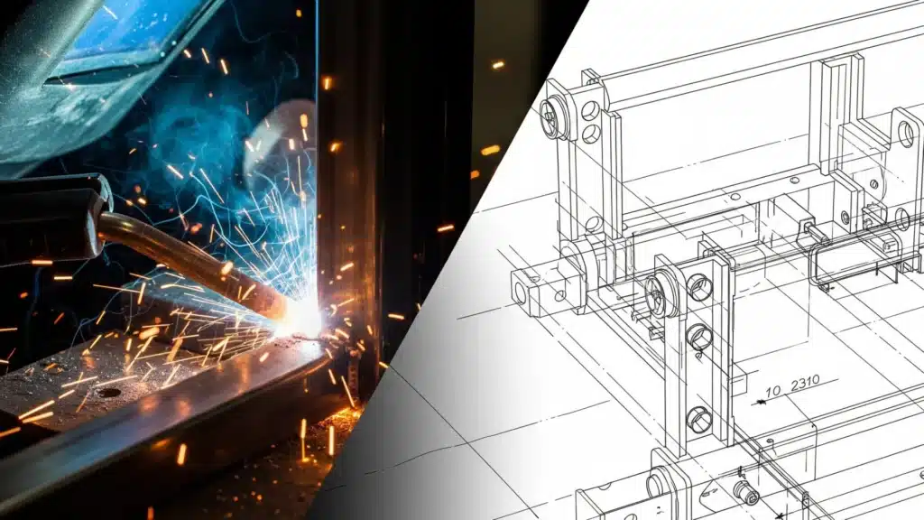
Processes and Capabilities

Flat Laser Cutting
We utilize 22kw fiber lasers to cut flat sheet and plate materials. The main limitation on our lasers is the size of the material that is readily available. We purchase coils directly from the mill on many sizes, so are able to get sheets that are 6′ x 12′ on many, but others may only have 5′ x 10′ available.
If there is a special project which requires a specialty material we’ll consider it, but there would need to be a real guarantee of selling a LOT of kits to accommodate stocking an additional material. The following are the stock materials and sizes we routinely carry.
Carbon Steel
Material Grade Definitions
ASTM A572 Grade 50
- Intended for: High-strength, low-alloy structural steel shapes, plates, sheet, and bars, generally used in structural applications requiring higher strength than A36.
- Yield Strength: 50,000 psi minimum.
- Common Use: Bridges, buildings, crane booms, construction equipment, and other structures where a higher strength-to-weight ratio is beneficial.
ASTM A36
- Intended for: Structural shapes (plates, bars, angles, etc.) generally thicker than 1/8 inch (3.2 mm).
- Yield Strength: 36,000 psi minimum.
- Common Use: Beams, columns, and structural shapes.
ASTM A1011 (formerly A569)
- Intended for: Hot-rolled sheet and strip, usually thinner than 1/8 inch (3.2 mm).
- Yield Strength: Varies by grade, but the A1011 Grade 36 is formulated to match A36 mechanical properties (36,000 psi minimum yield).
- Common Use: Sheet metal parts, light structural components, formed parts.
Stock Sizes
- A572 Grade 50 plate
- .1875″, .25″, .375″, .5″
- 72″ x 145″ plates
- Can accommodate up to 12′ long parts
- Even though 72″ is the spec, material is generally oversized so we can cut 72″ wide from it.
- A36 / A1011
- .06″, .075″, .10″, .12″, .135″, .75″, 1″
- 60″ x 120″ sheets / plates
- Plates are generally oversized a bit so the full 60″ x 120″ can be used.
Stainless Steel
Material Grade Definitions
304 Stainless Steel
- Intended for: General-purpose corrosion-resistant applications, available as sheet, plate, bar, tube, and structural shapes.
- Yield Strength: Approximately 30,000 psi minimum.
- Common Use: Food processing equipment, kitchen appliances, architectural trim, tanks, and chemical containers.
Stock Sizes
- 304 – Common stainless steel
- .06″, .075″, .10″, .12″, .135″, .25″
- 60″ x 120″ sheet / plate sizes
- Designs must be at least 1/8″ smaller than the sheet width or length as these materials are not oversized.
Aluminum
Material Grade Definitions
5052 Aluminum
- Intended for: Medium-to-high strength sheet and plate applications where good workability and corrosion resistance are required.
- Yield Strength: Approximately 28,000 psi minimum.
- Common Use: Marine components, fuel tanks, truck and trailer bodies, pressure vessels, and general sheet metal work.
Stock Sizes
- 5052 – Common aluminum with bending capabilities
- .04″, .06″, .08″, .09, .125″
- 60″ x 120″ sheet / plate sizes
- Designs must be at least 1/8″ smaller than the sheet width or length as these materials are not oversized.
Tube Laser Cutting
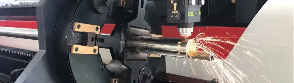
Although it’s called a “tube laser”, it would be more accurate to call it a 3D laser. These machines have chucks that can grip tubing, but they can generally cut anything that the chuck can grab. So round or square tubing work, but they can also cut angle materials, C-channel, or even beams.
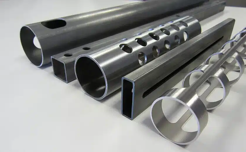
The following are the stock tubing materials and sizes we routinely carry.
Carbon Steel
Stock Sizes
- 1″ x 1″ x 16ga
- 1″ x 1″ x 11ga
- 1″ x 2″ x 16ga
- 2″ x 2″ x 16ga
- 2″ x 2″ x 11ga
- 2.5″ x 2.5″ x 14ga
- 2.5″ x 2.5″ x 7ga
- 3″ x 3″ x 14ga
- 3″ x 3″ x 7ga
Stainless Steel
Stock Sizes (304)
- 1″ x 1″ x 16ga
- 1″ x 1″ x 11ga
- 1″ x 2″ x 16ga
- 2″ x 2″ x 16ga
- 2″ x 2″ x 11ga
Aluminum
Stock Sizes (5052)
- 1″ x 1″ x 16ga
- 1″ x 1″ x 11ga
- 1″ x 2″ x 16ga
- 2″ x 2″ x 16ga
- 2″ x 2″ x 11ga
Forming and Bending
When designing parts for forming, it’s essential to account for material-specific bending behavior. Each material reacts differently under stress, so understanding the key bending parameters will help ensure accurate dimensions and prevent failure during manufacturing.
For Carbon Steel, Aluminum, and Stainless Steel, we typically define the bend using three main parameters: material thickness, bend radius, and the K-Factor. These parameters vary depending on the material type and the bend angle, and they directly affect the flat pattern dimensions.
Carbon Steel
| Thickness | Bend Radius | 90° K-Factor | 45° K-Factor |
|---|---|---|---|
| 16Ga (0.06″) | 0.03125″ | 0.45 | 0.44 |
| 14Ga (0.075″) | 0.03125″ | 0.39 | 0.44 |
| 12Ga (0.1046″) | 0.03125″ | 0.40 | 0.44 |
| 11Ga (0.1196″) | 0.125″ | 0.43 | 0.44 |
| 10Ga (0.1345″) | 0.125″ | 0.45 | 0.44 |
| 0.1875″ | 0.125″ | 0.45 | 0.44 |
| 0.25″ | 0.25″ | 0.45 | 0.44 |
| 0.375″ | 0.25″ | 0.45 | 0.44 |
| 0.5″ | 0.5″ | 0.45 | 0.44 |
| 1″ | 0.5″ | 0.45 | 0.44 |
Stainless Steel
| Thickness | Bend Radius | 90° K-Factor | 45° K-Factor |
|---|---|---|---|
| 16Ga (0.06″) | 0.03125″ | 0.45 | 0.44 |
| 14Ga (0.075″) | 0.03125″ | 0.45 | 0.44 |
| 0.10″ | 0.03125″ | 0.40 | 0.44 |
| 0.12″ | 0.125″ | 0.43 | 0.44 |
| 0.135″ | 0.125″ | 0.45 | 0.44 |
| 0.25″ | 0.25″ | 0.45 | 0.44 |
Aluminum
| Thickness | Bend Radius | 90° K-Factor | 45° K-Factor |
|---|---|---|---|
| 0.04″ | 0.03125″ | 0.33 | 0.44 |
| 0.06″ | 0.03125″ | 0.39 | 0.44 |
| 0.08″ | 0.03125″ | 0.27 | 0.44 |
| 0.09″ | 0.125″ | 0.31 | 0.44 |
| 0.125″ | 0.125″ | 0.45 | 0.44 |
Hardware
In the same way we stock specific materials, we also stock a lot of hardware. So again, when you’re designing things make sure – whenever possible – and use the hardware we stock so it can be fulfilled as part of the kit and people don’t have to run around and get extra specialty parts. Obviously, don’t make compromises! But, you know, if you can substitute without an issue please do.
Casters
We stock four different distinct casters. Below, you’ll find the description, 3D models and 2D
4″ casters – These casters work great for loads up to 1,000 pounds. They are great looking, and will last forever if not overloaded.
- Total Lock Swivel PLATE – These have a 300 pound per caster rating, and when they are locked it stops both the rotation and the swivel. They require 4 bolts to mount to a plate attached to the leg. This caster is stronger in terms of lateral force being applied.
- Total Lock Swivel STEM – These have a 300 pound per caster rating, and lock both for rotation and swivel. These thread into a nylon tube insert with a 3/8″ thread.
5″ Casters – Premium – Choose these if you need a high weight rating and full locking wheels.
- Fixed – These casters have a mounting plate that takes 4 bolts. They have a 2″ wide, flat poly coating over a cast iron hub. The color scheme is black on black, and they have an 800 pound per caster rating. They also have grease zerks to allow for ongoing upkeep.
- Total Lock Swivel – When they are locked it stops both the rotation and the swivel. They have a 2″ wide, flat poly coating over a cast iron hub. The color scheme is black on black, and they have an 800 pound per caster rating. They also have grease zerks to allow for ongoing upkeep.
6″ Casters – Ultra Premium: Choose these for the ultimate in smoothness and weight bearing.
- Fixed Suspension – These casters have a mounting plate that takes 4 bolts. They have a 2″ wide, flat poly coating over a cast iron hub. The color scheme is black on black, and they have a 1,200 pound per caster rating. They also have grease zerks to allow for ongoing upkeep.
- Locking Swivel Suspension – When they are locked it stops both the rotation and the swivel. They have a 2″ wide, flat poly coating over a cast iron hub. The color scheme is black on black, and they have an 800 pound per caster rating. They also have two grease zerks to allow for ongoing upkeep.
8″ Casters – Premium Heavy Duty: Choose these when you need a large caster to roll smoothly with a lot of weight on it.
- Fixed – These casters have a mounting plate that takes 4 bolts. They have a 2″ wide, flat poly coating over a cast iron hub. The color scheme is black on black, and they have a 1,200 pound per caster rating. They also have grease zerks to allow for ongoing upkeep.
- Total Lock Swivel – When they are locked it stops both the rotation and the swivel. They have a 2″ wide, flat poly coating over a cast iron hub. The color scheme is black on black, and they have a 1,200 pound per caster rating. They also have grease zerks to allow for ongoing upkeep.
Bolts / Nuts
We stock nuts, bolts, washers, split washers and nylon lock nuts in the following sizes:
Hex Head
- 5/16″-18
- 3/8″-16
- 1/2″-13
- 5/8″-11
Carriage Bolt
- 5/16″-18
- 3/8″-16
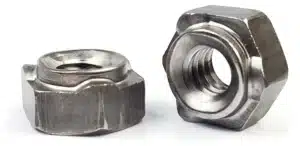
Weld Nuts
A weld nut is a specially designed nut with a wide base or protrusions that allow it to be securely welded to metal surfaces, creating a permanent, threaded attachment point for bolts or screws. Unlike normal nuts, these are designed purposefully for being welded in place. This is great when you have a situation where something needs to be bolted together, but you can’t reach the side where the nut needs to go. Weld one on and it’s always there.
We stock weld nuts in the following sizes:
- 5/8-16 Hex Weld Nut 3 projections (Short)
- 1/2-16 Hex Weld Nut 3 Projections (Short)
- 3/8-16 Hex Weld Nut 3 Projections (Short)
- 5/16-16 Hex Weld Nut 3 Projections (Short)
- 1/4-16 Hex Weld Nut 3 Projections (Short)
When you intend to have a weld nut added to a part, leave a hole clearance of 0.010″ – 0.030″ larger than the hole diameter, depending on fit tolerance and welding method.
For example: if your hex weld nut is 1/2″, cut a hole around 0.510″ – 0.530″ diameter.
Rivnuts (Rivet Nuts)
I wrote a post on the forums about RivNuts which gives an overview for those who aren’t familiar, but these serve the same function as weld nuts, but for thin material. Instead of welding them in place rivet nuts are compressed, like a rivet.
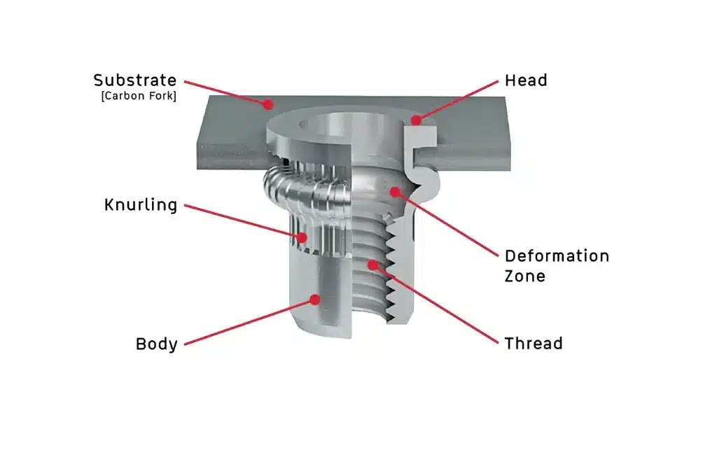
Rivnuts we stock include:
- 1/2″-13 – requires a hole size of: .69″
- 3/8″-16 – requires a hole size of: .55″
- 5/16″-18 – requires a hole size of: .43″
- 1/4″-20 – requires a hole size of: .39″
Tips and Techniques
Tabs and Slots
Whenever possible, EVERY single design we have should incorporate tabs and slots to add with assembly and add strength. This design methodology offers two huge benefits:
- Fabrication time is dramatically reduced – when everything snaps together it essentially eliminates all measuring. Generally, parts can be placed in their locations and held with magnets, clamps or small tack welds.
- Mechanical linkages add redundancy and strength – of course we want all welds to be perfect, but occasionally they fail, either partially or completely. If you have one piece of material poking through another it adds a margin of safety.
Generally speaking, when you design two parts to interconnect in this manner you want to leave at least .005″ of clearance all around at a bare minimum. However, if there is any dross on the edge of the material sometimes this amount of clearance won’t allow parts to fit without removing the burr or other material. Personally, when designing I like to make slots .025″ larger than the tabs going in them.
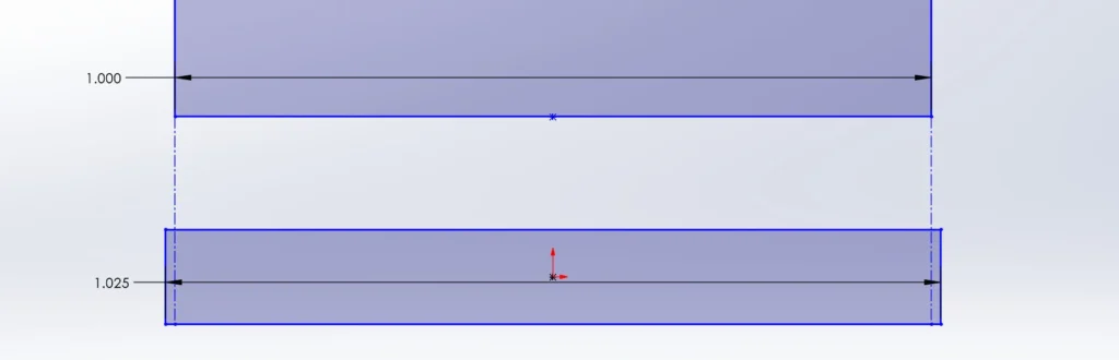
It leaves a little wiggle room, which gives the fabricator the freedom to deal with various inconsistencies by simply aligning the parts as they see fit.
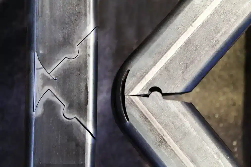
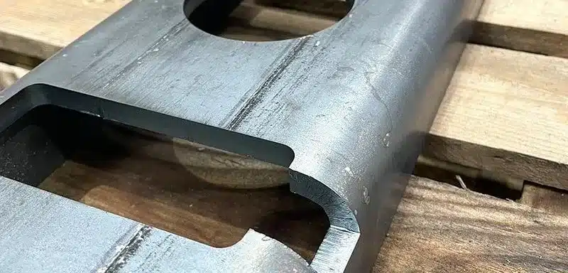
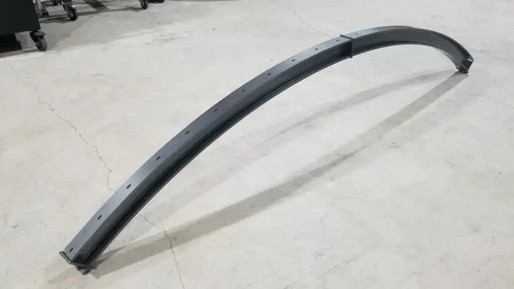
Tube Cutting Instead of Welding
Noe, one of our engineers, wrote an excellent post about utilizing the V-Notch Bending Principle. In a nutshell, if you need some tubing to form a right angle, instead of cutting two pieces and welding them together, you can cut a V-notch which leaves part of the tubing attached yet still allows you to bend it by hand and then weld the rest.
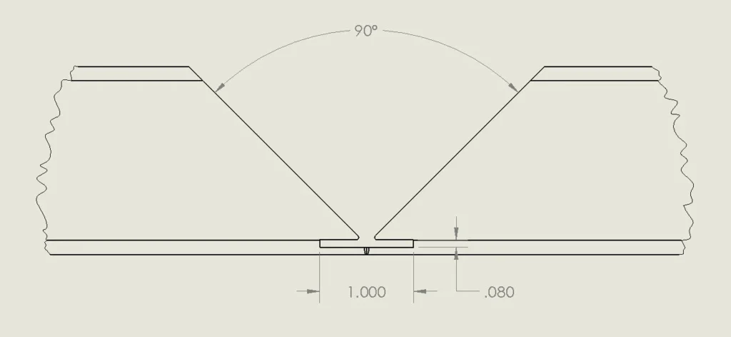
The profile of the cut can be played with to create different effects such as a much more rounded corner, or notches for positive engagement. The one issue with notches like the one below is that they will mess with seam welding. If that isn’t the plan, they are great.
Tube Cutting Instead of Bending
Let’s say we needed to create a small part which would usually require laser cutting and bending a flange or two… That part would require two different operations and need to be handled by two departments and multiple people. OR… if it could be cut directly out of a piece of tubing it could be done in a single operation!
This is one of those techniques that can’t be used all the time – but when it works out, it’s the most economical method since the tube laser can rotate the material and cut right around the 90 degree edges. If you have a product that uses small parts with flanges and you can even make minor design changes to incorporate it, it’s well worth it because it will significantly impact the cost of the part.
Adjust Tolerances for Paint or Powder
When parts are being welded together you don’t really have to worry about it, but it they are going to be assembled mechanically after they are coated make sure and leave extra tolerance in holes and slots to allow for the additional thickness.
Common paint thicknesses (DFT) for metal parts:
- Spray paint: 1–3 mils (0.001–0.003 inches) per coat
- Powder coat: 2–5 mils (0.002–0.005 inches) per coat, often up to 8 mils for heavy-duty
- Industrial/epoxy paints: 2–6 mils per coat
- Automotive finishes: 0.8–1.2 mils per coat, but with multiple layers (primer, base, clear), total is often 4–6 mils
What this means:
- One normal spray-painted coat = ~0.002 inches
- One powder coat = ~0.004 inches
Key notes:
- Thickness is per coat. Multiple coats add up.
Eliminate Sharp Points and Edges
We recommend breaking all sharp points in your designs for two reasons:
- It’s safer – why leave super sharp points when you can easily chamfer them. Taking the edge off minimizes uncomfortable encounters.
- Prepare for coatings – if you intend to paint or powder coat metal you need to prep all of your edge to eliminate sharpness and burrs. Those will inhibit adherence and cause premature failure.
Incorporate Plug Welding
When designing you always need to be thinking about how much welding will be needed, as well as where it should be located. And in some cases a plug weld might be a great option. For example, our ARCHE Table Base utilizes them extensively.
Essentially, there are a series of holes cut in the upper plate which allow you to fill in the hole while making contact with the material below. For even better engagement you can have a tab poking 1/2 way through the hole!